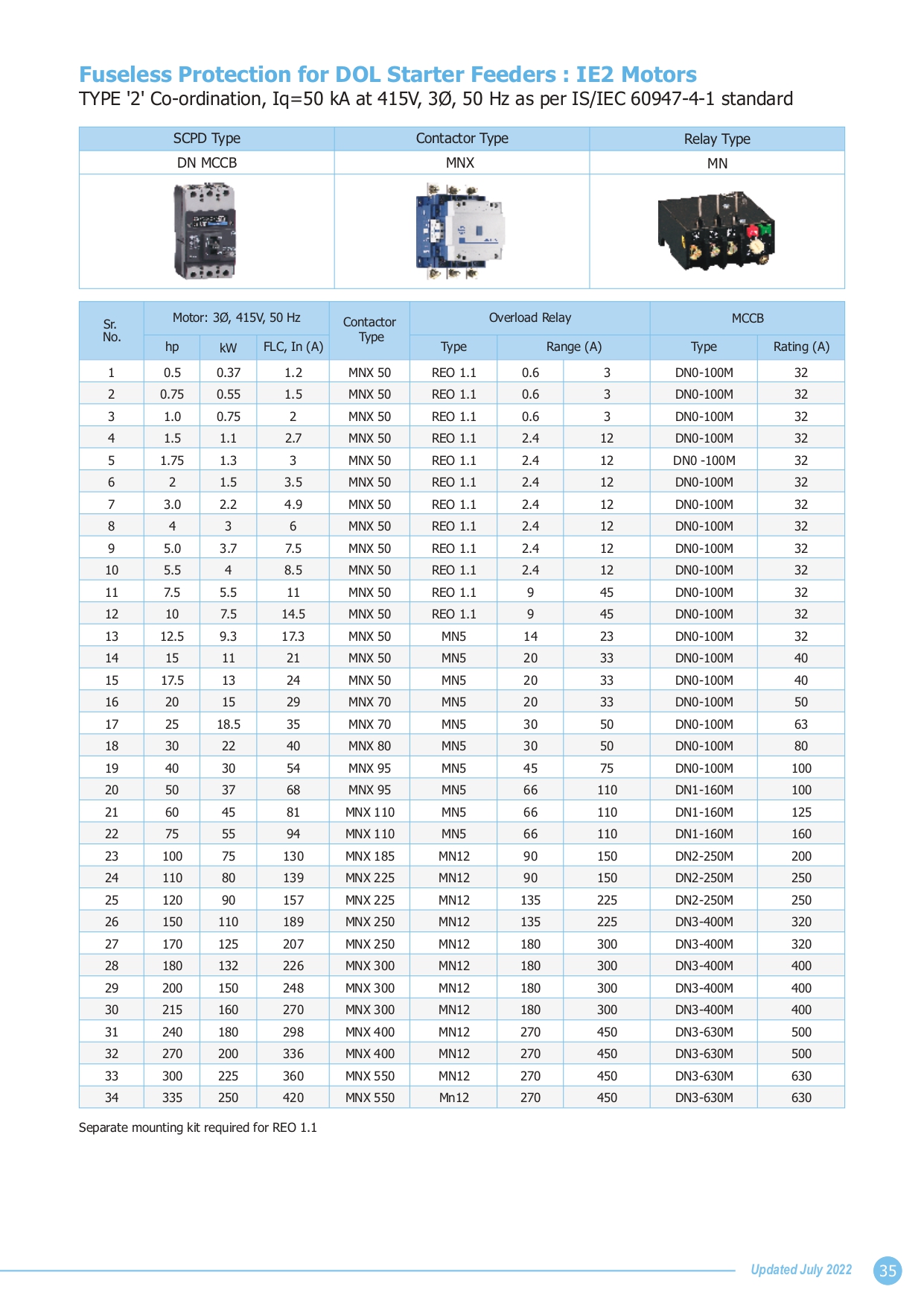
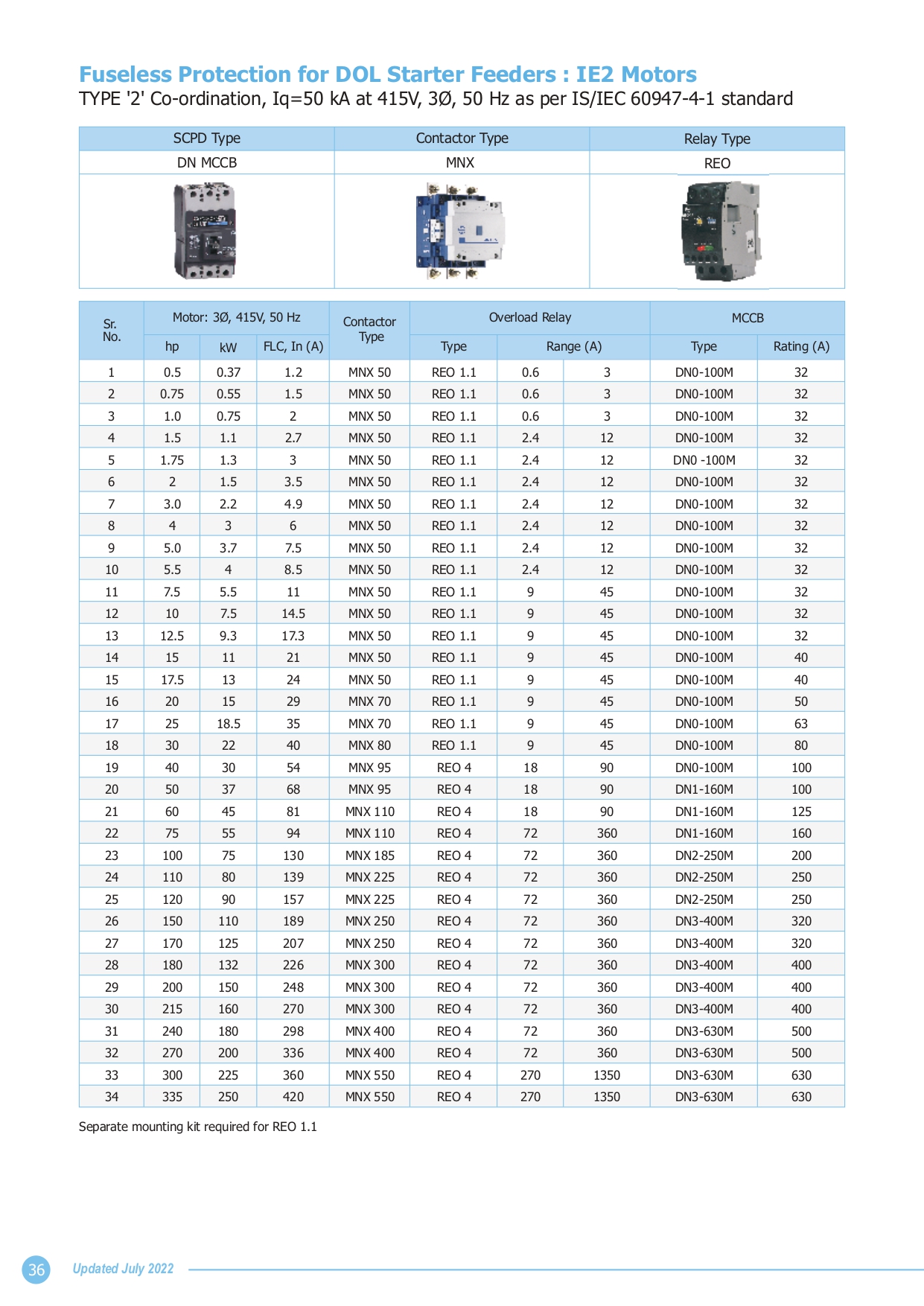
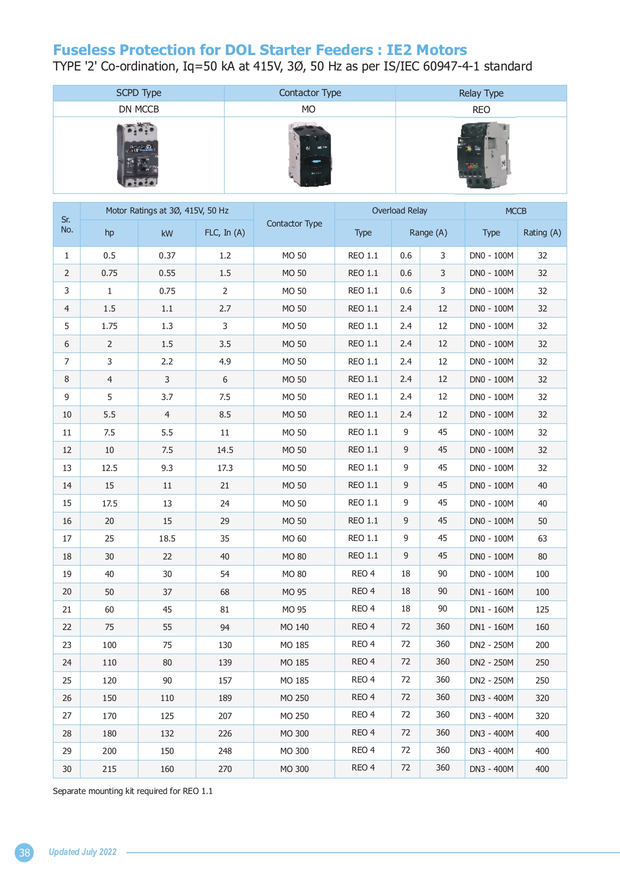
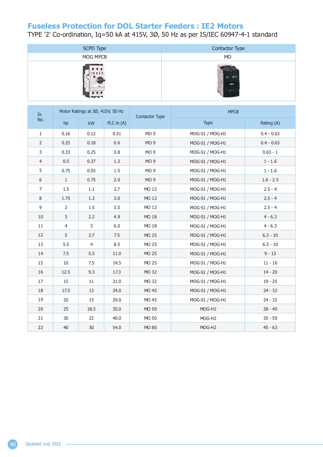
The Calculation of Reactive Energy Based on the Application
Power Factor Correction for Transformer no-load compensation
The transformer works on the principle of Mutual Induction.
The transformer will consume reactive power for magnetizing purpose.
Following equivalent circuit of transformer provides the details of reactive power demand inside the transformer:
Power Factor Correction where Load and present
Power Factor is Known
The objective is to determine the requested reactive power Qc (kvar) to be installed, in order to improve the power factor cosφ and reduce the apparent power S.
For φ’ < φ, we’ll get: cosφ’ > cosφ and tanφ’ < tanφ
This is illustrated on the diagram in the left.
Qc can be determined from the formula : Qc = P. (tanφ - tanφ‘), which is deduced from the diagram.
Qc : power of the capacitor bank, in kvar
P : active power, in kW
tanφ: tangent of the phase angle - before compensation,
tanφ‘: tangent of the phase angle - after compensation
The parameters φ and tanφ can be obtained from the billing data, or from direct measurement in the installation.
The following table can be used for direct determination.
Example:
Consider one 1000kW motor with cosφ 0.8 (tanφ = 0.75).
In order to get cosφ’= 0.95, it is necessary to install a capacitor
bank with a reactive power equal to
k x P, i.e. : Qc = 0.42 x 1000 = 420 kvar
Every Cable is unique in its appearance, utility and even performance. Your cable requirements are also unique. To calculate the exact sizes of the cables as per your requirements we can use this cable size calculator. Use it to calculate various cable sizes.
** Please confirm the data before proceeding for actual application. The actual data may differ due to different conditions.**